Author(s): Ton Schoenmaker
For years the way of producing a flow profile for Inspection Chambers and Manholes could be divided into 3 methods: Injection moulding, Roto moulding and Hand assembling. For the standard orientations, for example straight through and cross, the IM profile integrated with a base is by far the best option. But for nonstandard configurations; different orientations, inlet heights and inlet sizes, the only option is to hand weld them together from injection moulded parts, pipes and plates. This is a time- consuming way of producing with high production cost and often aesthetic-wise of a challenging level. This is not necessary anymore after the introduction of 3D printing as a new production method for flow profiles in chambers and manholes. 3D printing is in many industries an accepted production method which can produce parts of high quality and high accuracy. The printing systems have faced a huge development in the last 10 years and prints are often close to perfection. The only disadvantage of these printing systems is the maximum size of the print. But since the introduction of 3D robot printing, products with a diameter of 1 meter can be printed without any problem. 3D robot printers were up to recently, used for prototypes, one- off products and art objects. Now a production area is created on which multiple products can be produced in a row without human interference. The most common materials used for 3D printing are ABS and PLA. These materials have good adhesion, almost no shrinkage and a good appearance. Unfortunately, these materials are not common in our industry. We need PP, PE or PVC. While our manholes and inspection chambers are from PP, we also need PP flow profiles. The advantage of using a 3D robot printer is that it uses granulates instead of filaments or special powder. This makes the material cost part almost equal to injection moulding. Another advantage is also that recycled material can be used. Own scrap can be used but also waste from other markets. The main reason that flows profiles are ideal for 3D printing is that nonstandard flow profiles are very labour-intensive. So, 3D printing really helps out here. Besides that, there is a lot of freedom in design. This helps to design in such a way, that the final profile is hydraulically optimal. This prevents the overflowing of manholes during heavy rain showers. Of course, these products should fulfil all requirements of the EN13598-2. Even though major development steps have been made in 3D printing during the last 5 years, 3D robot printing is still in the exploring phase and we find many hurdles on our way. This paper will show how our industry can use 3D printing and what are the pros and cons.
The use of plastic as a base material for inspection chambers and manholes started already in the early 80s. An important part of these chambers is the flow profile which directs flows in sewage and stormwater system in the right direction. Common production methods for this flow profile are injection moulding, roto moulding and often hand assembling. The disadvantage of the first two production methods is: you need moulds. Which is only feasible for standardised shapes, sizes and orientations of which you can sell multiple numbers. Otherwise, you have to fall back on the third method: hand assembling, in other words; hand welding them together from injection moulded parts, pipes and plates. This is a time-consuming way of producing with high production cost and often aesthetic-wise of a challenging level.
This is not necessary anymore after the introduction of 3D printing as a new production method for flow profiles in chambers and manholes. The advantage of 3D printing is that you are more or less free in shaping your profile so you can make it hydraulically optimal which enables us to optimize the flow in our systems.
While used in many fields, 3D printing is not very commonly used in our industry. One of the reasons is that, for now, the only usable material is PP and while it is a relatively new production method, it is also not mentioned as a possible production method in the EN13598-2 the standard for Inspection chambers and manholes. Despite this fact, the printed profiles should fulfil all the requirements of 13598-2. This has been thoroughly tested and passed.
Additive manufacturing (AM), also known as 3D printing, is a process in which a three-dimensional object is built from a computer-aided design (CAD) model, usually by successively adding materials in a layer-by-layer fashion
Fused deposition modelling (FDM) is the most widely used form of 3D printing at the consumer level. FDM works by extruding thermoplastics, such as ABS and PLA, through a heated nozzle, melting the material and applying the plastic layer by layer to a build platform
3D printing is a way of additive manufacturing. This is in many
industries an accepted production method which can produce
parts of high quality and high accuracy. The printing systems
have faced a huge development in the last 10 years and prints are
often close to perfection.
The most known 3D print methods are:
• Fused Filament Fabrication - FFF (Ultimaker)
• Selective Laser Sintering - SLS.
• Stereolithography - SLA.
Products made by SLS and SLA are of high quality and are even used for medical purposes such as facial implants and heart valves. For our industry, these methods are, for the moment, only usable for small series or prototypes because of the complicity of the print devices and production costs.
The FFF method is a filament-based way of printing and is more commonly used. It is a relatively easy and cheap way of making prototypes. The disadvantages of this system are the long printing time up to 24 hours and the high cost.
The other disadvantage of the above-mentioned printing systems is the maximum size of the print of often not bigger than 30x20x30 cm. But since the introduction of 3D robot printing, product size is unlimited. Even 12-meter-long boats have been printed. Robot printers can use normal granulates therefore the method is described as FGF (Fused Granulate Fabrication). Besides the unlimited printing size, this is a huge advantage because of the low material cost. No special powders or filaments of 20 to 100 euros per kilo are needed. Even recycled material is possible to use.
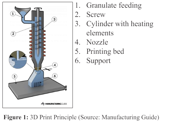
These granulates are used by a big extruder (see figure 1) with an output of up to 24 kg per hour. 3D robot printers were up to recently, used for prototypes, one-off products and art objects.
The most common materials used for 3D printing are ABS and PLA. These materials have good adhesion, almost no shrinkage and a good, smooth, appearance. Unfortunately, these materials are not commonly used in our industry. Materials used in our business are usually PP, PE or PVC.
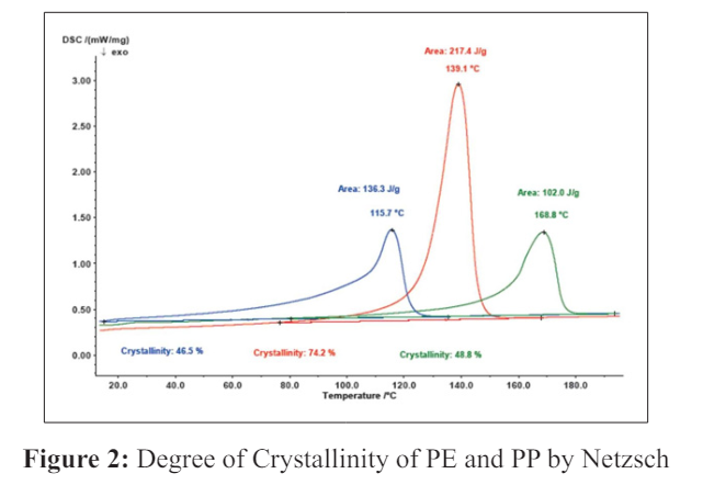
For 3D printing, PP is the most mature of these materials. Using PE is still difficult. That&rsquo:s because the crystallization point of PE is at a much lower temperature than that of PP (see figure 2). That means that you have to wait longer before you can lay a new layer on top of the previous layer because you need the resistance of the last layer to get good adhesion between the two printed layers.
We focused therefore on Polypropylene. Challenges:
• Shrinkage
• Warpage
• Adhesion
Polyolefins do have a certain shrinkage. For Polypropylene it's around 2%. With the free-forming process of 3D printing, this results in warping. Because contrary to injection moulding where the produced item is cooled within the mould until the product is reaching the state of crystallinity, the cooling process of a 3D printed product is in the open. Without any measures, this results in extreme warping of the product. The solution is adding a percentage of glass fibre The glass fibre causes a certain resistance against shrinkage and warping.
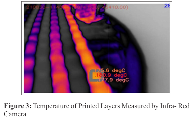
Second challenge to overcome is the adhesion between the printed layers. The temperature of the last layer should not be too hot because it is not crystalized yet, so the same problem will arise as when printing with PE, with no resistance to press the new layer on. When the temperature is too low and you will get a cold weld which also results in bad adhesion. The optimum temperature is between 120 and 150 degrees Celsius. The temperature of the last layer is depending on the size of the product and the welding speed. The welding speed is depending on the complexity of the product. The fewer curves there are the faster you can print. A printer has always to slow down at a sharp curve otherwise the extruder is drawing the layers from the last one because the layers have not been connected.
With an optimal product, the printing speed could be so high that the temperature of the last layer has not been cooled down enough when the next layer is applied. Therefore, you can add cooling vents. By controlling the temperature, the vents know exactly how strongly to cool. The temperature of the printed layers can be measured with an integrated IR camera (figure 3).
For 3D robot printing, flow profiles are ideal products to start with. With injection and roto moulding, we are more or less limited to the shape of the moulds we have bought. These are the most commonly used configurations which are applicable in certain countries, especially countries where the sewage and stormwater network started to grow more recently. But in several countries, the first networks are getting replaced already. In this case, connections can come from every direction, in every dimension and at different heights. In these countries, this kind of inspection chamber can be more than 50% of the market. Usually, these connection challenges are solved with a ball bottom or with a hand-welded solution.
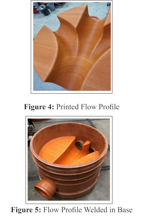
Besides that, this is a labour-intensive way of producing which is getting more and more challenging at a time when manpower is getting scarce. With 3D printing, the printer is doing the work and your employees can do the finishing touch. This results in a product appearance which never can be reached with normal hand assembly (figures 4 & 5).
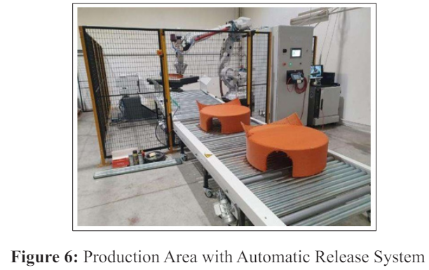
As mentioned before, up to now 3D robot printing has been used for art, prototypes or one-offs. To make 3D robot printing realistic for production you need to automize. As shown in the picture below it is possible with an automatic release system. By introducing an automatic release system (see figure 6), a production area can be created on which multiple products can be produced in a row without human interference. This system enables you to print after working hours and does not stop until the print is manually released.
With the current intensification of heavy showers, the handmade flow profiles are not optimal for our stormwater system. In this case, you would like to have a flow profile which is the most optimal for the specific combination of inlets to be able to release the water as fast as possible out of your system. The freedom of design of 3D printing gives us the possibility to create and produce this optimal flow profile.
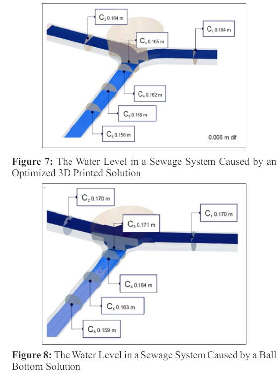
Deltares, a well-known independent institute in the Netherlands for applied research in the field of water and subsurface, has been asked to calculate the difference in flow-specific energy between a ?standard? non-standard flow profile solution, in this case, a ball-shaped profile, and an optimized solution.
The optimized flow profile (figure 7) showed 23% less head loss compare to a ball bottom flow profile (figure 8) as you can see in the pictures below. This will reduce the chance of flooding on the occasion of heavy rainfall.
From several additive manufacturing methods, it is known that
the finished products are strong, sometimes even stronger than
an injection moulded product. How about 3D robot printing? As
mentioned before the adhesion between the printed lines is the
biggest challenge for FDM printing and could therefore also be
the weak point for this process. To get more knowledge about the
strength of the prints the following tests were performed:
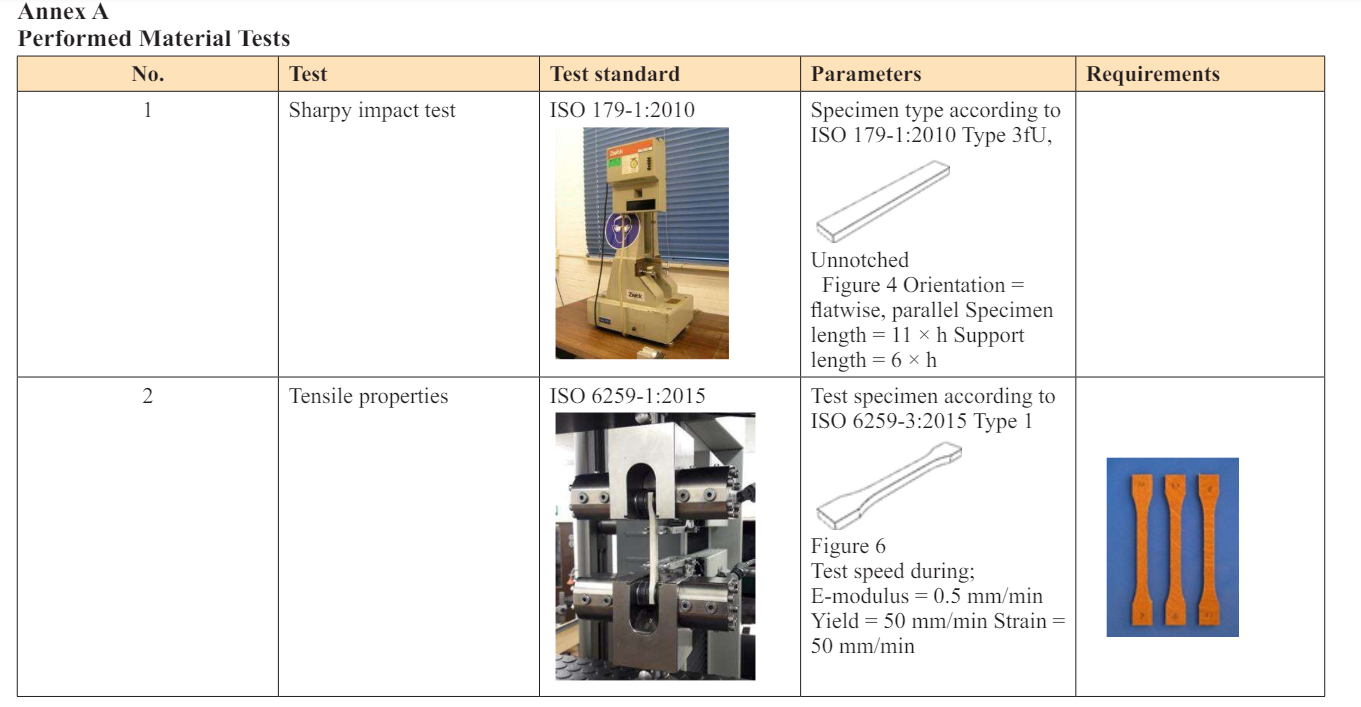
• Tensile Test According to ISO 6259-1:2015 [1].
• Sharpy Impact Test According to ISO 179-1:2010 [2].
The printed plates arrived in two different versions concerning the orientation of their weld lines. One plate has its weld lines stacked straight on top of one another, the other plate has them stacked at an angle of 45 degrees. From each series of printed plates, two different sets of samples were milled concerning the orientation of the weld lines. This ultimately results in 4 sets of test samples, each with a distinct orientation of their weld lines. They are presented as type A, B, C, and D.
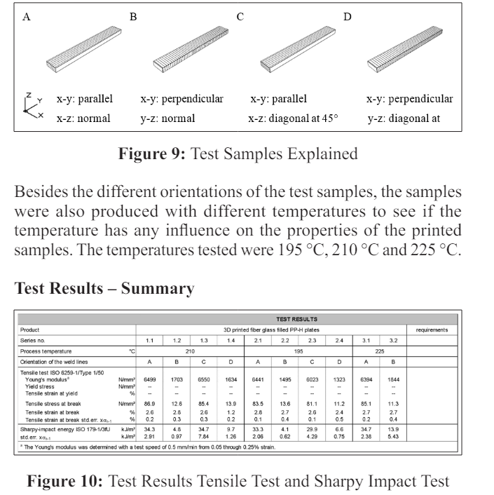
Overall, the conclusion was that the 3D printed samples were 4 times stronger parallel to the printing direction than perpendicular. Nevertheless, the perpendicular direction is still strong due to the added glass fibre. For the sharpy tests, the difference was even bigger. Here the added glass fibres made the products more brittle [1-3].
The tests performed were
• Structural integrity at -0.5 bar, according to EN13598-2 [3].
Test method Annex C and ISO 13267
• Impact test according to EN13598-2 Annex D. Striker D90
with a mass of 1kg, fall height 2.5m to hit the centre point
of the flow profile.
• Durability test at -0.147 bar at 80°C for 3000hr. (non-standard
material) according to EN13598-2 Annex A Table A.1
• All the above tests are fulfilled.
Even though major development steps have been made in 3D printing during the last 5 years, 3D robot printing is still in the exploring phase. But we see that there are several products in our business where 3D printing is an add-on to our traditional production methods with which we can solve labour shortages and improve the quality of our production. Because of the freedom of design, flow profiles are ideal products to start with. Reaching the quality required for our products took a lot of effort, especially to optimize the adhesion between the printed layers and we are still making improvements. The products produced do fulfil all requirements of the EN13598-2. The next step is to add 3D printing as an accepted production method in the applicable standards. After that, there is nothing in our way to extend the range of printed products in the piping business and preferably add PE as the next applicable material.
