Author(s): Wei Wang and Yongjian Sun*
Stepper motor is an electrical pulse signal converted into angular displacement of electromechanical components, motors will each receive an electric impulse a step angle of rotation, and therefore also called step motor stepper motor or pulse motor. The design STC89C51 microcontroller as the core to build a stepper motor drive system, through I/O port output timing of the square wave signal as a control stepper motor drive signal through Darlington ULN2003 stepper motor drive. Then through an external keyboard circuit, thyristor display circuit can be achieved on the stepper motor acceleration and deceleration, reversing, effective control of start / stop.
Mastering the control system design and debugging technology of stepper motor has both engineering significance and practical value [1].
Because the function of the microcontroller is very powerful, can design peripheral circuits, so the design is to achieve the control of various operating states of the stepper motor through the STC89C51 microcontroller, drive circuit, button circuit, display circuit, etc., including the start, stop, acceleration, deceleration and speed display of the stepper motor [2].
As early as the 1920s, the British invented the stepper motor [3]. Due to the relative backwardness of China's scientific and technological level, until the 50s of the last century, the research and production of stepper motors has just started, but there are still few institutions that conduct research on stepper motors. By the 1960s, stepper motors had been widely used in production. By the late 1960s, there had been a great breakthrough in the research of stepping motor in China, and great progress had been made in the research and development of driver technology. At the same time, the research and development of reactive stepping motor also reached a new level. From the middle and late 1970s to 1980s, it was the development stage of batch production of finished stepping motors in China, and various new motors were also developed [4]. Since 1990s, scientific research institutes have done a lot of research on precise models of stepping motors, and various stepping motors and drivers have been widely used in most industries [5].
We have a big gap with foreign countries in the drive equipment, mainly reflected in their control theory and analysis of AC motors and application capabilities are relatively strong [6]. If there is an advanced control theory as the basis, the software program written can better control the AC motor inside the controller. In summary, although the stepper motor has very low requirements for the conditions of application, it is not suitable for application on high-power equipment [7].
Stepper motor is the received electrical pulse signal into a motor rotor angle displacement of an electromechanical component, stepper motor every time a pulse is received will rotate a step angle, so the stepper motor is also called a step motor or pulse motor. Because the stepper motor has the characteristics of fast start and stop, its application is very extensive, such as plotters, copiers, automatic recording instruments, clocks and watches and other devices or systems.
Reaction stepping motor, hybrid stepping motor and permanent magnet stepping motor are three commonly used stepping motors at present, and they are introduced below. Reaction type stepping motor adopts high magnetic conductivity material to form toothed rotor and stator. Its structure is simple, production cost is low, step Angle can be made quite small, generally three-phase, can achieve large torque output, step Angle is generally 1.5 degrees, but noise and vibration are very large.
The rotor of permanent magnet stepper motor adopts cylindrical permanent magnet with multiple magnetic poles and is equipped with toothed stator outside. With the rotor and stator between the attraction and repulsion force to produce rotation, its output is large, dynamic performance is good, but the step Angle is generally relatively large.
Hybrid stepper motors are a combination of the advantages of permanent magnet and reactive motors. It is divided into two phase and five phase this stepper motor is the most widely used, it is a composite product of PM and VR, its rotor uses tooth rare earth permanent magnet material, stator is tooth protruded structure.
1. Step angle θ s . Step Angle is the Angle that the rotor turns after the stepping motor receives a pulse signal. θs is an actual mechanical Angle, and the starting and operating frequency of the stepper motor are affected by θs .
Static step Angle error δθs . Static step Angle error is the value of the difference between the actual measured step Angle and the theoretical step Angle. Generally, the percentage of the theoretical step Angle is used to measure the size of δθs
Maximum static torque Tmax. Tmax refers to the maximum value of torque characteristic of stepping motor under specific conditions. i. Tmax= KZs ZR LFδ 2 λ1 (1) It can be seen from formula 2 that when the winding current increases, Tmax also increases. Generally speaking, Tmax refers to the calculated value after each phase winding is energized with rated current. The ability of stepping motor with load is positively related to its maximum static torque. Therefore, improving the output torque of stepping motor and manufacturing power stepping motor are the important development directions of stepping motor at present.
Starting frequency f and starting moment frequency characteristics.
The starting frequency refers to the maximum pulse frequency at which the stepper motor can start without losing its step. The starting frequency is one of the main performance indicators of stepper motors
Operating frequency and running moment frequency
characteristics.
When the control pulse frequency rises after the stepper motor
is started, the maximum frequency of operation without losing
step is called the operating frequency
Rated current
When the stepper motor does not rotate, the maximum current
that can pass through each phase winding is called the rated
current.
Rated voltage
Single voltage type: 6V, 12V, 27V, 48V, 60V, 80V
High and low voltage switching type: 60/12V, 80/12V
Every time the stepper motor receives a pulse signal, the motor rotor will rotate a step angle, and the more the number of pulse signals received by the stepper motor, the greater the angular displacement of the stepper motor, so the stepper motor speed and pulse frequency are positively correlated. In the case of normal operation, the stepper motor speed is only related to the pulse frequency, and has nothing to do with other external conditions, such as temperature, air pressure, vibration, etc
1. Single voltage drive
.Only providing a directional voltage drive mode for the stepper
motor winding is called single voltage drive. When a high level is
applied to In, a large base current is generated, so that the triode
T works in the saturation region, and if its saturation voltage drop
is not counted, then the power supply voltage will all act on the
motor windings. When the ind is supplied low, the triode is in the
cut-off state and no current is flowing through the motor windings.
Although this circuit structure is simple, low cost, few components,
and high reliability, although it has these advantages, when
the resistor is connected in the circuit, the power consumption
increases a lot, making the overall efficiency of the power drive
circuit low. Therefore, the power drive circuit is only suitable for
stepper motors with small power.
2. High and low voltage drive.
The high and low voltage drive mode can make the motor winding
quickly reach the preset current value after powering on, and the
motor winding current can be quickly reduced to 0 after the power
off, and the efficiency is relatively high.
3. Self-excited constant current chopper drive.
In order to control the winding phase current, the motor winding
current value is converted to a voltage to compare with the D/A
converter setpoint. Because the chopping frequency is not very
stable, it will make the motor windings stir up a higher surge
voltage, which will cause greater interference to the control circuit,
which will not only produce oscillations, but also reduce system
reliability.
4. It excitation type constant current chopper drive.
The oscillation problem can be solved by adding a constant
frequency clock to the D flip-flop to deal with the surge voltage
problem caused by the self-excited chopping frequency, which is
called the excitation constant current chopper drive.
5. Segmentation drive mode
High resolution, high positioning accuracy, small step angle and
good starting performance are several advantages of subdivision
drive, and this method can also greatly reduce the low-frequency
vibration of stepping motor and reduce the working possibility of
motor in resonance region. Compared with other driving methods,
subdivision driving is a major breakthrough in stepping motor
driving technology.
According to the working principle of stepping motor, it can't be directly connected to the power supply, so if you want to work normally, you must rely on stepping motor driver. The stepper motor controller can send a pulse signal, and for each pulse signal received, the stepper motor rotates a step angle.
Whether the stepper motor driver emits pulses and the level of the pulse frequency determine whether the stepper motor rotates and the speed of the rotation. The controller can also signal direction to determine whether the stepper motor is forward or inverted. When the stepper motor driver accepts the controller step pulse as well as the direction signal, the control circuit generates a preset motor excitation winding on or cut-off signal. The power drive section amplifies the signal emitted by the controller.
The winding of the stepper motor is a coil wound on the core, and the motor winding has two inherent properties of resistance and inductance, which have a great impact on the performance of the motor.
The inductor and resistor are connected in series to form a stepper motor phase winding. When t = 0, a voltage is applied to the circuit, which is the current characteristic in the circuit:
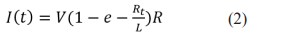
The rate of change of the initial winding current of the energized is:
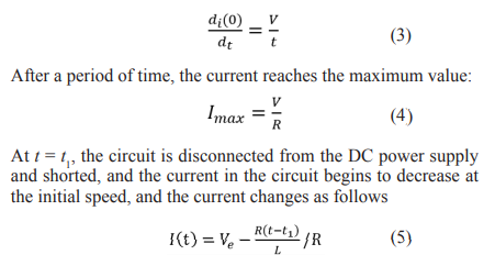
The current at the low frequency time can reach the maximum value, and when the rectangular wave frequency rises to the critical frequency, the current gradually drops from the maximum value to the maximum value, and after the frequency exceeds the critical value, the current in the motor windings does not become the maximum value. Since the stepper motor torque size is positively correlated with the motor winding current, the stepper motor can reach its rated torque when running at low speed, but when it is higher than a specific frequency, the higher the frequency, the lower the winding current, and the smaller the motor torque, which weakens the load capacity of the stepper motor when running at high speed.
Single chip microcomputer (SCM) is a simplified computer system that integrates some important components of microcomputer on the same chip. Because SCM has the advantage of high integration, the signal transmission distance in the system is significantly reduced, the structure configuration is improved, and the running speed of SCM is also significantly increased.
Single-chip microcomputer needs to expand its external application in order to give full play to its powerful function. Although the single-chip microcomputer has a very powerful function, but subject to its internal structure, we can only expand to construct the actual single-chip microcomputer application system to adapt to different working conditions.
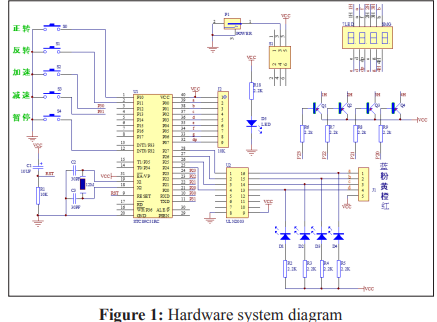
Figure: 1 shows the overall diagram of the hardware system. In this design, STC89C51 microcontroller is used as the core processor, Darlington driver ULN2003 is used as the stepping motor driver, and DC-5V stepping motor is used. The first bit of the four-bit LED digital tube shows the direction of the motor, and the third and fourth bits show the gear number of the motor running speed. There are five small red lights, one of which is used as the power indicator, and the other four indicate the speed of the motor. P1 port is the input part of the signal which is connected with the key circuit. There are five key inputs, and the corresponding functions are: forward rotation, reverse rotation, acceleration, deceleration, start/stop. P0 port is connected with digital tube to realize display function. P2 is the signal output part connected with the stepping motor driver.
The clock circuit is like the heart of the computer, which can control the working frequency of the computer. If you increase the clock frequency, the CPU will run faster. This time, the crystal frequency is 12MHz.
The reset circuit can be used to initialize the internal circuit of the single chip microcomputer, also can initialize all the components of the system, and let it run again from the initial state. By designing the peripheral circuit, the reset function of the single chip microcomputer can be realized.
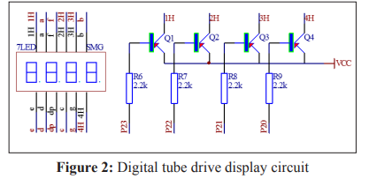
Because light-emitting diodes are very cheap, they are widely used in microelectronic fields such as household appliance collars. As shown in figure 2, this design uses a four-digit tube with a common anode to display the steering and gear of the stepper motor, and a transistor is used to drive the digital tube.
The key circuit can be used to transmit commands and input data to the single-chip microcomputer, and it is the main means to realize man-machine dialogue.
The keyboard is actually a collection of key switches, and the switches used are elastic switches that make use of the closing and breaking action of mechanical contacts.
In the process of opening and closing, the key switch will make the voltage jitter, the time is usually 5 to 10 ms; the middle of the two jitters is the closed state, and the closing time is determined by the speed of the keystroke, and the opening state is before the first jitter and after the second jitter.
The output voltage is high when the key is closed and low when the key is off. We can check whether the key is open or closed by detecting the high and low state of the output level. In this design, the high level corresponds to the button being disconnected, while the low level corresponds to the button being closed. In order to ensure that the microcontroller on the button action accurate response, we must eliminate the adverse effects of jitter. Thereare two ways to eliminate key jitter, one is to use the hardware method, the other is to use the software method. Because the hardware vibration elimination circuit design is more complex, so this design did not use this method.
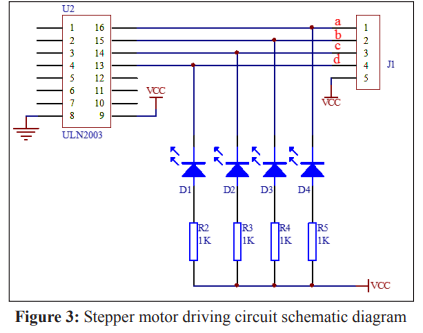
The purpose of this design is to efficiently control the rotation of the stepper motor, so we need to change the pulse sent by the MCU into the stepping Angle, so as to control the rotation of the stepper motor. Here we use darlington driver ULN2003 to provide pulse signal for the stepper motor. ULN2003 application circuit is mainly used in intelligent instrument, PLC, solenoid valve, servo motor, stepper motor and other fields.
According to this design goal, we need to write the control step motor start/stop, deceleration, positive &negative, keyboard input and digital tube display program, the software of the control system of step motor must be implemented at the same time read the keyboard, keyboard signal processing, control of stepping motor rotation, control, digital tube display this a series of actions, the interrupt technology is needed for help.
1. Read button subroutine
Scan the keyboard ports in the query mode and compare them
with the initial value. If they are equal, it means there is no key
action; if they are not equal, software shake elimination is carried
out to confirm whether there is a key action. After a delay of 10ms,
scan again and compare with the initial value again. If it is equal,
it indicates that the last unequal is caused by jitter; if it is equal,
it proves that there is indeed a key action.
2. Key processing subroutine
Timer T0 controls the output of the pulse signal. If the timer T0
is turned off, the output of the pulse signal will be blocked. By
starting and stopping timer T0, the start and stop control of the
stepping motor can be realized.
The current speed of stepper motor determines the interrupt time of timer interrupt program. The current motor speed is used to control the interrupt time of the timer, and then the pulse output frequency is controlled.
Finally, the speed of the stepping motor is controlled. The level of the detection direction control bit can control the switching sequence of the leading end of the stepper motor, so as to control the steering of the stepper motor.
Stepping motor control system simulation, after the completion of the hardware and software for alignment inspection coordination operation and realization of system design at the beginning of the targets set by the questions and the system is running at record analysis, if can't achieve the goal is to modify the software program is part of the system, until meet the design needs.
The design idea of this system is: first complete the functional modules required by the system, and then complete the assembly of each functional module according to the hardware system and software system, and finally connect these two parts to complete the whole system and debug.
The main problems encountered during the debugging of the hardware system are as follows:
The way to shake the software, and the control of time. After completion of the program design of the software system and debugging hou I found the system of the stepper motor speed range is too small, after consult relevant information I found the thinking of the original design is not reasonable, so in the original basis to improve the program, the keyboard consists of the main program to deal with, the rotation of the stepper motor controlled by the timer, The speed of stepper motor is determined by the timer timing time. In this way, the problem is solved, which not only enlarges the speed control range of the stepping motor, but also makes the control of the stepping motor speed more accurate.
After powering on the welded circuit board, press the power button and the start button successively and find that the stepper motor does not respond. At first, I thought that the circuit had a virtual welding problem, so I checked the circuit board again after powering off the circuit board with a multimeter, but there was no problem. The program is also correct when carefully checked. Later, I looked at the working principle of the stepper motor again in the data and found that it was necessary to make clear its four-phase sequence before the normal positive and negative rotation of the stepper motor. After several more tests, the phase sequence of the stepper motor was finally found to be A, B, C and D. The circuit board was rewired and welded in accordance with this phase sequence, and the stepper motor was found to rotate normally after being energized again.