Author(s): Jessica Sjah*, Ryan Sulistian, Ayomi Dita Rarasati and Bambang Trigunarsyah
In earthquake-prone regions, it's crucial for hospitals to be well-prepared to ensure that medical care continues without interruption for the victims. The utilization of precast structural systems in construction, particularly in earthquake-prone areas like Indonesia, offers numerous advantages including enhanced construction efficiency and resilience against seismic loads. However, ensuring effective connections between precast components is crucial for structural integrity, especially in the event of earthquakes. Traditional methods of construction project planning often lead to interdisciplinary discrepancies and delays. Building Information Modeling (BIM) presents a solution to streamline construction practices and minimize clashes between disciplines. Despite its potential benefits, the adoption of BIM in Indonesia's construction industry has been slow due to various barriers. This research aims to evaluate the integration of BIM in the structural analysis and design of a Hospital Building in Indonesia. By conducting a comparative evaluation of structural analysis with and without BIM integration using ETABS and Revit-RSA software, this study seeks to enrich the understanding of BIM's role in enhancing the design of precast structural buildings, particularly for critical infrastructure such as hospitals. Quantitative and qualitative assessments will be conducted to evaluate various parameters including story mass, natural period, internal forces, and clash detection, thereby contributing to the body of knowledge regarding BIM utilization in Indonesia's construction sector.
Hospitals are crucial facilities in responding to victims of natural disasters, including earthquakes, and must be adequately prepared to accommodate numerous individuals with critical conditions. Time is of the essence in saving the lives of victims, underscoring the imperative for hospitals to remain operational following earthquakes, thereby ensuring ongoing medical care for patients [1].
The implementation of precast structural systems in Indonesia has seen significant growth, being widely utilized not only in building construction but also in infrastructure such as roads and bridges [2]. Construction using precast concrete offers several advantages over cast-in-situ concrete, including quality, time- effective construction, architectural flexibility, and sustainability [3-6]. Furthermore, precast structural systems have shown effective performance in withstanding earthquake loads [7-10]. The connection system in precast concrete construction is a critical aspect to ensure strength and ductility equivalent to monolithic concrete when subjected to earthquake loads [11-13].
Precast concrete component connections are categorized into two types: dry connections and wet connections [14]. Precast connections utilizing dry connection types do not require on- site casting, thereby enhancing construction efficiency [15]. Dry connections can be implemented through bolted connections, welded connections, and prestressed connections [15-19]. Conversely, precast connections utilizing wet connection types require on-site casting of concrete or higher-grade grout to fill the joint. Wet connections offer higher efficiency levels compared to dry connections [5]. Therefore, wet connections will be utilized in this study.
Construction project planning involves various complex aspects and requires interdisciplinary cooperation to achieve intricate goals [20]. Knowledge, experience, and collaboration are essential for successfully planning and implementing a construction project according to plan. However, there are often interdisciplinary planning discrepancies that can impact the budget, structural calculations, or lead to construction schedule delays [21]. These discrepancies arise due to weak coordination and collaboration between disciplines [22]. The conventional method of checking interdisciplinary clashes, such as overlaying transparent 2D drawings on a light table and manually identifying clashes visually, is highly susceptible to human error [23].
Digitalization within the construction industry remains relatively low compared to other sectors, thus the adoption of BIM has the potential to enhance and streamline construction practices [24,25]. According to BS EN ISO 19650-1:2018, BIM involves the use of a shared digital representation of assets created to facilitate the design, construction, and operation processes, serving as a reliable basis for decision-making. BIM in the Architectural, Engineering, and Construction (AEC) industry can optimize workflow, foster design creativity, reduce errors, enhance quality, shorten construction timelines, lower overall costs, facilitate collaboration between disciplines, and enable multidimensional visualization and lifecycle management of buildings [20,26- 29]. Building Information Modeling (BIM) can be utilized in construction projects to minimize clashes between disciplines [30].
The Level of Development (LOD) denotes the degree to which the geometry of elements has been planned and the reliability of information project team members can rely on when using models. LOD encompasses several levels indicating the extent to which a system has been planned, ranging from a conceptual plan to the representation of a perfectly constructed system. These LOD levels include LOD 100, 200, 300, 350, 400, and 500 [31].
The adoption of BIM initially started in Indonesia in 2012, whereas it had already begun in developed countries as early as 2000 [32,33]. The utilization of BIM within the construction sector and related research in Indonesia remains limited and progresses slowly [34]. The first research paper related to BIM (Building Information Modeling) in Indonesia was published in 2013. From 2013 to 2021, there were only a total of 11 publications recorded [33]. Indonesian construction practitioners have implemented BIM Level 1 without possessing proper knowledge of BIM [35]. The top five barriers to BIM implementation in Indonesia are the lack of BIM training, insufficient BIM experience and capability, absence of client demand, high costs associated with software and hardware acquisition, and inadequate IT facilities [35].
In Indonesia, the structural analysis design of buildings is predominantly carried out by consultants using independent structural analysis codes such as ETABS, SAP2000, or Midas. In this study, a comparative evaluation of structural analysis with and without BIM integration will be performed due to gravitational and seismic loads using ETABS and BIM software, namely Revit- RSA (Robot Structural Analysis), in a case study of a Hospital Building. The seismic loading approach methods used in this study include the Equivalent Static Method and the Response Spectrum Method. Previous research has compared ETABS and Revit, but the quantitative results were limited to the volume of reinforcement [36,37]. In this study, the story mass, natural period, story shear, story drift, internal forces, 3D visualization, reinforcement detailing, material volume calculations, and clash detection using BIM will be evaluated. This research will enrich the number of publications regarding the use of BIM in Indonesia. Moreover, this study conducts both quantitative and qualitative research regarding the utilization of BIM in the design of precast structural buildings, particularly for Hospital Buildings.
The object under study is a four-level hospital with a building height of 16.2 meter and a total area of 4852.75 square meter, located in Bogor, Indonesia. It utilizes a special moment resisting frame structural system and is classified under seismic design category D The hospital building's structure is modeled using ETABS software based on the Finite Element Method. Subsequently, a BIM model will be created in Revit software and analyzed using Robot Structural Analysis (Figure 1).
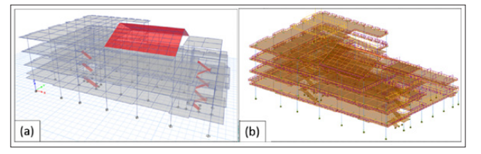
Figure 1: Hospital’s Building Structure Numerical Model by (a) ETABS, and (b) Revit-Robot
Precast concrete components are employed for the slabs, beams, and columns connected using the wet joint method. The construction of precast concrete structures in Indonesia is governed by specific regulations outlined in SNI 1726:2019, SNI 1726:2020, SNI 2847:2019 and SNI 7833:2012, which adopts the American Standard ACI 318-14. The level of development (LOD) reached level 350, encompassing detailed physical and structural modeling of the joints between components [31].
In Revit-RSA software, both physical (3D visualization) and analytical models of structures are integrated into a single model as part of BIM integration. The structural components are modeled thoroughly to match the detailed architectural drawings accurately. Structural analysis against gravitational and seismic loads can be conducted in RSA directly from this model. In this study, the results of story mass, natural period, story shear, story drift, and internal forces obtained by RSA will be compared to ones modeled by ETABS. The Revit will be utilized to demonstrate the reinforcement details and evaluate concrete volume. The concrete volume calculation results based on the BIM model were analyzed against manual calculations. The 3D visualization, reinforcement detailing, and material volume calculations of a building can be easily and quickly obtained (efficiently) when using BIM integration.
There exists a significant difference in story mass between the 1st floor and the roof, reaching 105.35%. ETABS and RSA employ different definitions for stories: ETABS considers both the upper and lower halves of the column as the story mass, while RSA only considers the full length of the lower column and disregards the upper column as explained in previous research in [38]. Consequently, the first floor or ground floor in RSA lacks mass entirely, whereas in ETABS, it is regarded as half the height of the ground floor column. Similarly, differences in story definition exist on the roof floor, mirroring those on the ground floor. On intermediate floors, the difference in story mass is below 5%, as presented in Table 1, primarily attributable to variations in volume calculations of structural components occupying the same space. Despite the significant variation in mass between the ground floor and the top floor, the difference in total mass is below 2%.
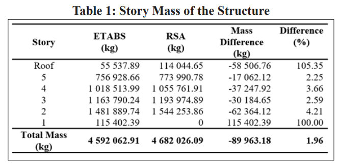
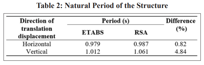
The difference in story mass and total mass of the structure influenced the natural period of the building. The natural period of the building obtained from RSA was slightly higher than one obtained from ETABS (Table 2) because of the larger mass resulted in RSA while the stiffness remains similar.
The difference in story shear resulting from the static equivalent and response spectrum methods obtained from ETABS and RSA is minimal on the first floor but increases notably on the top floor, as shown in Table 3 and Table 4. This pronounced difference at the uppermost level stems from variations in story definition, as discussed earlier, leading to significant differences in seismic load distribution based on the effective seismic weight.
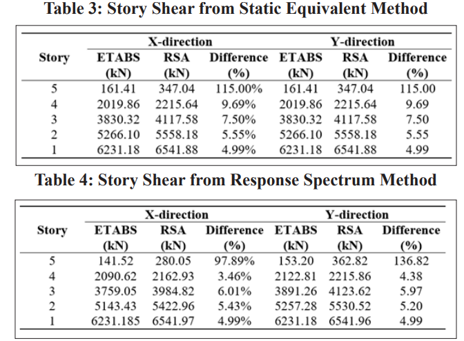
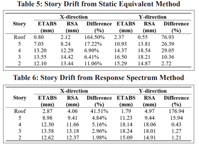
Table 5 presented the story drift, indicating that both the static equivalent and response spectrum methods from ETABS and RSA models exhibited an increasing percentage error at upper levels in both directions (Table 5 and Table 6). This trend occurred due to the significantly greater story mass on the top floor in the RSA model compared to that in the ETABS model.
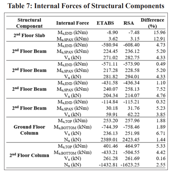
As shown in Table 7, the difference in internal forces between ETABS and RSA was less than 10% for beam and column elements, but for slabs, it reached up to 15%. The magnitude of slab’s internal force appears relatively minor compared to that observed in beam and column internal forces.
The reinforcement design is completed based on the Indonesian code SNI 2847:2019 using ETABS and RSA. With BIM Software Revit-RSA, the structural modeling of the hospital building from RSA (Figure 2(a)) can be integrated with Revit to provide 3D visualization both for the entire building (Figure 2(b)) and partially (Figure 2(c)).
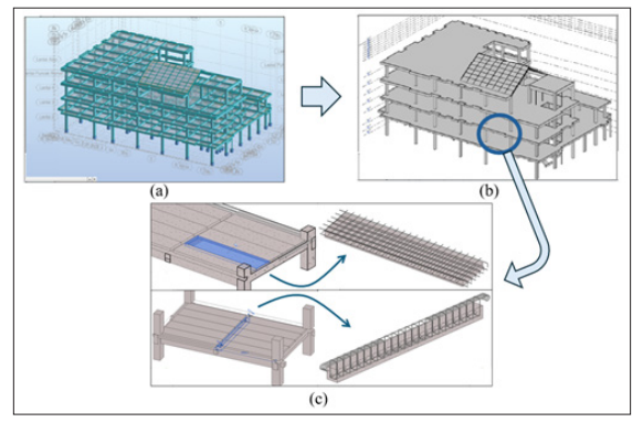
Figure 2: Hospital’s Building Structure by Revit-RSA (a) Numerical Model by RSA, (b) 3D Visualization of Hospital Building by Revit, and (c) 3D Visualization of Precast Slab and Beam Elements by Revit
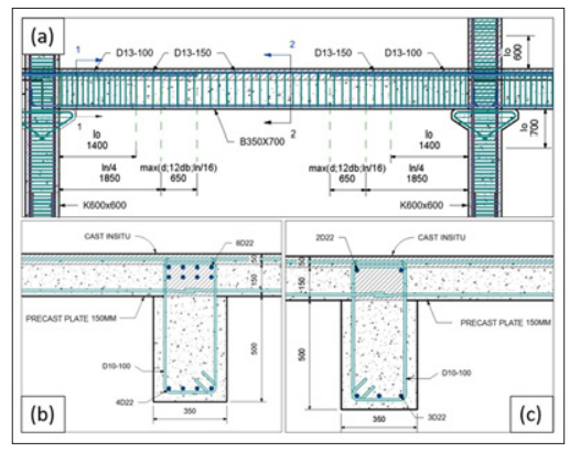
Figure 3: Beam Reinforcement Detail : (a) Longgtudinal Section,(b) End Section, and (c) Middle Span Section
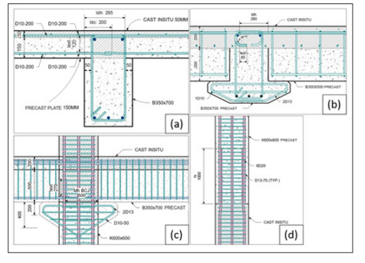
Figure 4: Reinforcement Detail: (a) Slab-beam Joint, (b) Primary- secondary Beam Joint, (c) Beam-column Joint, and (d) Column- column Joint
Revit can also provide technical detailed drawings illustrating each reinforcement, such as reinforcement details on beams or wet joint connection systems. (Figure 3 and Figure 4). This can effectively save time, costs, and labor, as also mentioned in [36,37].
The concrete volumes of slabs, beams, and columns obtained from manual calculations were compared to those from Revit. From manual calculation, slab volumes were estimated by calculating the areas covered on each floor and then multiplying by the thickness. The concrete volume of slabs was not reduced by any overlapping volume with other structural components. The concrete volume of slabs obtained from Revit was almost similar to that obtained from manual calculations with difference below 0.1% as shown in Table 8.

The manual calculation of concrete volume for beam elements yielded smaller values of 1.5% than those obtained from Revit. This is because exterior beams and stair beams have more complex overlapping volumes that are difficult to precisely estimate, resulting in a higher percentage of error compared to other beam types (Table 9). Additionally, the concrete volume of beams in Revit is reduced by overlapping volume with columns, while manual calculations consider the full length of the beam.
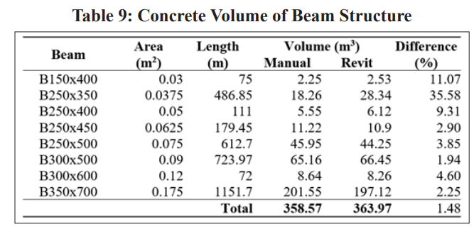
Concrete volume calculated manually for columns yielded larger values of 4.0% than those from Revit. This is because the column's volume is reduced by overlapping with slab elements in Revit, while manual calculations consider the full length of the column element (Table 10). The total concrete volume obtained from manual and Revit analyses is shown in Table 11, with the percentage of difference below 1%.
The main difference between the modeling process with and without BIM implementation lies in the integration of the physical and analytical models into one BIM model. This model can be used to statically and dynamically analyze structures, model reinforcement details based on the analysis, calculate concrete volume, produce engineering drawings, and provide 3D visualization. Outside the scope of this research discussion, the BIM model can integrate aspects of other disciplines such as architecture and MEP (Mechanical, Electrical, and Plumbing).
In contrast, an independent structural analysis model without the implementation of BIM can only be used for structural analysis. Detailed engineering drawings must be carried out separately from the analytical model, and the calculation of concrete volume is also done separately. Furthermore, there is no detailed 3D visualization of the structure beyond LOD 200 to check for any potential clashes.
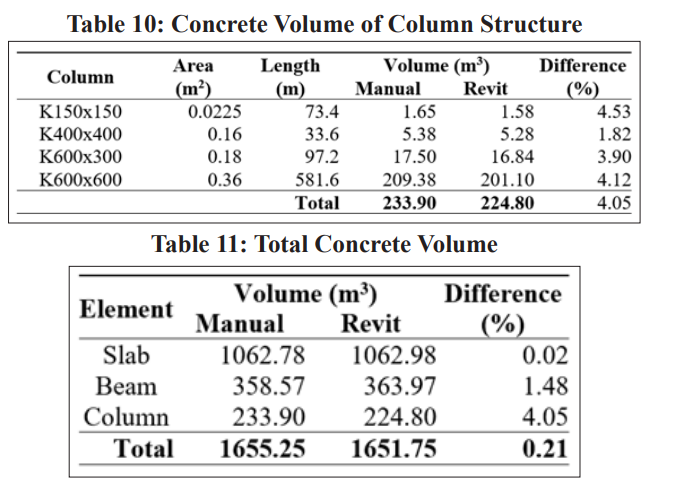
During the process of detailing precast components in Revit's physical model, the 3D visualization of the structure using the BIM model reveals that precast slab components, typically one meter in width, cannot be utilized. This is because the precast slabs, with their long-span sides supported by beams (Figure 5), will occupy the same space as the reinforcements of precast beams. Consequently, adjustments to the width of the clashing slabs are necessary. This clash was only detected through the 3D visualization of the physical model, as the ETABS independent structural analysis model in 3D only reached a development level of 200 with simple geometry and could not capture the geometric details of precast concrete components. In research conducted by, similar hard clashes were encountered when using the BIM model for physical modeling [39,40].
Figure 5: Precast Slab-beam Interface 3D Visualization The modification in the width of precast slabs due to hard clashes
is integrated into various engineering drawings that depict this aspect, including the slab cross-section, slab-beam joint, and 3D view of the slab-beam joint (Figure 6). If AutoCAD Software is employed as a drawing tool, adjustments to each engineering drawing must be made individually. Working in isolation without utilizing BIM integration significantly increases the likelihood of clashes occurring [41]. This integration significantly streamlines the process of generating engineering drawings, especially when modifications are made during the design phase. Designing and drawing processes without BIM implementation are susceptible to hard clashes like this going unnoticed due to the limited 3D visualization with detailed geometry [42].
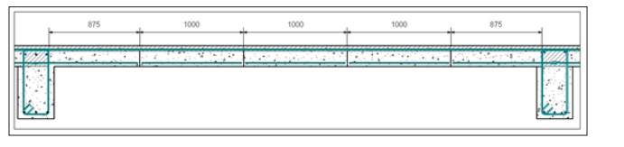
Figure 6: Precast Slab-beam Section
Story shear and story drift resulting from static equivalents as well as response spectrum analysis between ETABS and RSA exhibited significant differences on the highest story level, surpassing the difference of 105.35% observed on other floors due to variations in story definitions.
The BIM hospital model comprises physical and analytical models capable of static and dynamic structural analysis, as well as detailed modeling of reinforcement and precast components up to LOD 350. Engineering drawings corresponding to model changes can be generated directly from the physical model without the need for additional drawing tools or software.
Manual calculations of concrete volume estimates can still serve as planning references despite a difference of 0.21% compared to Revit's estimates. However, it is essential to note relative differences, particularly when reviewing beam or column components. Physical modeling in Revit facilitates 3D visualization of shapes, quantities, locations, and relationships among various components, thus aiding in the identification of clashes within the physical model.
The primary difference between the modeling process with and without BIM implementation lies in the integration of physical and analytical models. This integration enables static and dynamic structural analysis, detailing of reinforcement based on analysis results, concrete volume calculations, production of construction drawings, and 3D visualizations to detect potential clashes. Without BIM, the structural modeling process halts at structural analysis, requiring separate procedures for producing engineering drawings, designing reinforcement, and calculating concrete volumes, without detailed 3D visualization to assist in clash detection.
Construction project planning should embrace BIM to facilitate seamless integration of work processes, especially considering the involvement of multiple disciplines. This integration helps avoid time-consuming and costly clashes discovered during implementation.
An alternative approach to integrate structural planning and construction management is through the use of the CSIxRevit plug-in, which integrates ETABS or SAP2000 structural models with Revit to generate physical models [37]. This alternative eliminates the need for structural engineers to learn new software and allows them to continue using ETABS or SAP2000, which are more commonly utilized in Indonesia.
This research is funded by Directorate of Research and Development, Universitas Indonesia under Hibah PUTI 2022 (Grant No. NKB-318/UN2.RST/HKP.05.00/2022).