Author(s): Nilesh D Kulkarni* and Saurav Bansal
The paper presents a detailed examination of the application of Unified Modeling Language (UML) for system analysis within the context of a restaurant business case study. It begins with the articulation of business requirements through user journey understanding and user story definition. The importance of a good user story is emphasized, with a particular focus on the INVEST characteristics that ensure a user story's effectiveness. The paper further delves into the basics of UML, exploring fundamental concepts such as classes, and the various relationships within class structures including association, aggregation, and composition. Additionally, it discusses the significance of polymorphism and interface design in object-oriented programming. The paper also highlights Object-oriented design (OOD) heuristics, which provide developers with a set of guidelines for making informed design decisions. A comprehensive user story, constructed from the restaurant use case, demonstrates the practical application of these concepts. This is followed by the development of corresponding UML diagrams, including a use case diagram, an activity diagram, and a state diagram, which collectively showcase the robust modeling capabilities of UML in capturing complex system requirements and providing a clear pathway for system design and implementation.
Requirements engineering (RE) is a discipline that defines a common vision and understanding of socio-technical systems among the involved stakeholders and throughout their life cycle [1,2].
A system requirements specification, often referred to simply as a "requirements specification," is a technical document that delineates and structures the aspects and considerations of these systems from the perspective of requirements engineering (RE). An effective requirements specification brings forth numerous advantages, as documented in the literature [2-4]. These include -
The software development process commences with requirements engineering, a phase of paramount significance. In the seamless progression of software development, the effective gathering of requirements assumes a pivotal role, as emphasized in reference [5]. Efficient requirements not only lead to the development of a streamlined system but also contribute to cost-effectiveness in the final product.
Requirement elicitation marks the inaugural phase of requirements engineering, wherein all relevant users and stakeholders of the system convene to extract fundamental system requirements [6]. This process of requirement elicitation encompasses another pivotal aspect of requirements engineering, which is requirement gathering. Requirement gathering consists of specific steps outlined in reference, including requirement elicitation, requirement analysis, requirement documentation, requirement validation, and requirement management [5].
Requirements gathering serve the dual purpose of catering to both technical and business stakeholders, and as a result, they are typically crafted in natural languages. Natural languages are indeed chosen for this purpose because they offer a high level of communicative flexibility and universality. Humans are proficient in employing natural languages for communication, which makes them resistant to adoption issues as a technique for documenting requirements.
The data for this paper was sourced from well-regarded academic databases, such as Google Scholar, IEEE Xplore, journals, and studies. We performed thorough searches using keywords like ‘User Story, ‘Use Case’, ‘UML notations and 'UML diagrams'. This method enabled us to uncover a wide array of sources that could potentially contribute to our study.
Agile is an iterative and flexible approach to software development and project management that emphasizes collaboration, customer feedback, and the ability to adapt to changing requirements.
Agile is the ability to create and respond to change. It is a way of dealing with, and ultimately succeeding in, an uncertain and turbulent environment. The authors of the Agile Manifesto chose “Agile” as the label for this whole idea because that word represented the adaptiveness and response to change which was so important to their approach [2,7].
A user story, is a way of expressing a software requirement from the
perspective of an end-user or customer [8]. User stories are short,
simple descriptions of a feature told from the perspective of the
person who desires the new capability, usually a user or customer
of the system. Kent Beck, creator of extreme programming (a
software development methodology) developed the concept of
stories. Kent’s simple ideas was to stop - stop working so hard
on writing perfect document, and to get together to tell stories.
In early 2000, Rachel Davies at Connextra build a story telling
template after multiple experiments 'AS a
• Role: A user story describes a specific role or persona who interacts with the software. This helps in understanding who will benefit from the feature.
• Goal: Each user story outlines a goal or objective that the user wants to achieve with the software. It focuses on the "what" and "why" of a feature rather than the "how."
• Benefit: User stories also highlight the value or benefit that the user will gain from the feature. This helps in prioritizing and understanding the importance of the user story.
Jeff Patton emphasizes the importance of ongoing conversations and collaboration between development teams and stakeholders to clarify and refine user stories. This iterative process ensures a shared understanding of the business requirements [8].
Characteristics of a good user story are explained with an acronym INVEST which represents a set of criteria used to evaluate and write effective user stories in Agile software development.
Independent: User stories should be independent of each other. This means that they should be self-contained and not rely on the completion of other stories. Independence allows for flexibility in prioritizing and sequencing stories.
Negotiable: User stories should be negotiable, meaning that they are open to discussion and can be refined through collaboration between the development team and stakeholders. They should not be overly prescriptive or rigid.
Valuable: Each user story should deliver value to the end-users or customers. It should focus on solving a real problem or meeting a specific need. Value helps prioritize stories based on their impact.
Estimable: User stories should be estimable, meaning that the development team can reasonably estimate the effort required to implement them. This helps with planning and resource allocation.
Small: User stories should be small or appropriately sized. They should not be too large or complex. Small stories are easier to understand, implement, and test. They also allow for more frequent delivery of functionality.
Testable: User stories should be testable, which means that there should be clear and measurable acceptance criteria associated with each story. These criteria define when the story is considered complete and working as intended.
The first versions of UML were created by “Three Amigos” - Grady Booch at el defines “The Unified Modeling Language (UML), is a standardized visual language for specifying, constructing, and documenting the artifacts of software systems. It provides a set of diagrams and notations to represent various aspects of software design and architecture, allowing software engineers to communicate, visualize, and model complex systems effectively.”
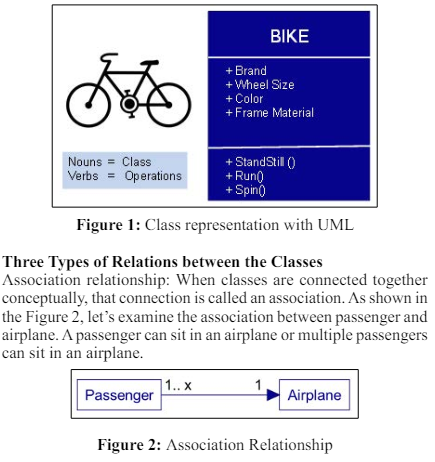
A class is a blueprint for creating objects. It defines a set of properties and behaviors that the instantiated objects (instances) will have. A class encapsulates data for the object and methods to manipulate that data. The Figure 1, shows the UML standards for representation of a Bike class, with the name of the class shown in the first block, properties like brad, wheel size, color shown in the second block and the operations that a bike class can perform like standstill, run and spin in the third block. Classes can be categorized based on their purpose and functionality in the system:
Concrete Class: These are classes that can be instantiated into objects. They provide a full implementation of all methods and properties declared within them.
Abstract Class: An abstract class cannot be instantiated on its own and is intended to be subclassed. It may contain abstract methods with no implementation. These methods must be implemented by non-abstract subclasses.
Utility Class: A class that contains a set of static methods and is not intended to be instantiated. It usually provides helper functions.
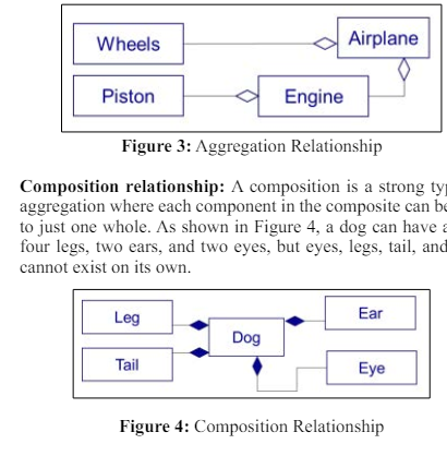
Aggregation Relationship: This is a special type of relationship, used to model situations where one class (the whole) contains or is composed of other classes or objects (the parts), and theparts have a lifecycle that is independent of the whole. As shown in the Figure 3, next examine the aggregation relationship, an engine (whole) can have many Pistons (parts) similarly an airplane (whole) can have multiple engines (parts) as well as an airplane can have multiple wheels (parts).
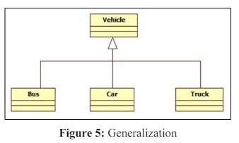
In this relationship one class (the child class or subclass) can inherit attributes and operations from another (the parent class or superclass). The generalization allows for polymorphism. In generalization, a child is substitutable for parent. That is anywhere the parent appears, the child may appear. The reverse isn’t true [9]. As shown in the Figure 5, signifies that "Bus," "Car," and "Truck" inherit from "Vehicle." They are expected to share common characteristics or behaviors that are defined in "Vehicle." For instance, if "Vehicle" has attributes like 'number of wheels' and 'fuel type' and operations like 'start engine ()', then "Bus," "Car," and "Truck" would inherit these operations and attributes.
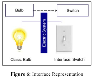
An interface is a set of operation that specifies some aspect of classes behavior, and it’s set of operation class presents to other classes [9]. As shown in Figure 6, the "Electric System" is considered an interface between the light bulb and the light switch. The "Electric System" serves as a contract between the light bulb and the light switch, stipulating that when the switch is turned on, the bulb should light up. Interfaces are used to decouple the implementation and the abstract design, allowing for changes in implementation without affecting the system that uses the interface. Similarly, the light switch and bulb are decoupled from each other, you could replace either the bulb or the switch without needing to change the other, as long as they both adhere to the same electrical system standards. Interface also allows different classes to be treated through a single interface type, the electric system could work with any device that conforms to its standards, not just a light bulb. This could include a fan, a heater, or any other electric device that can be turned on or off.
Object-oriented design (OOD) heuristics are guidelines or best practices that aid developers in making design decisions during the object-oriented software development process. These heuristics are not strict rules but are based on the collective experience of seasoned software engineers. They help in creating designs that are modular, reusable, maintainable, and understandable [10]. Some well-known OOD heuristics include -
• Encapsulation: Keep data and the methods that manipulate that data together
• Modularity: Design systems that have well-defined, independent, and interchangeable modules.
• Hierarchy: Utilize inheritance and composition to promote reusability and scalability.
• Low Coupling: Ensure that objects or classes are independent of each other, minimizing the impact of changes.
• High Cohesion: Keep related and similar functionalities grouped together, ensuring that each class has a single purpose or responsibility.
• Polymorphism over Conditional Statements: Use polymorphism rather than conditional statements to handle different types based on the same interface.
• Design for Extension: Design components so that they can be extended, rather than modified, to accommodate new features.
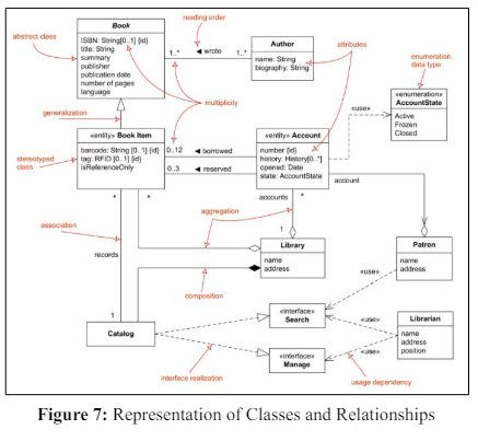
The Figure 7, shows all the concepts discussed in the previous section, as explained below -
• Classes and Attributes: There are several classes such as Book, Author, Account, Library, Patron, Catalog, and two interfaces Search and Manage. Each class has attributes that define its properties. For example, the Book class has attributes like ISBN, title, summary, etc.
• Abstract Class: The Book class is an abstract class, indicated by the italicized name. This means it is not instantiated directly but serves as a template for other classes.
• Stereotyped Class: Book Item is a stereotyped class, specialized as an «entity», which means it is an object that will be stored and managed in the system. It inherits from Book.
• Generalization: The arrow from Book Item to Book indicates inheritance or "is-a" relationship, meaning that Book Item is a type of Book.
• Associations: There are associations between classes, depicted by solid lines. For example, a Book is associated with an Author, and an Account is associated with a Library.
• Multiplicity: The numbers near the association lines indicate the multiplicity of the relationship. For instance, an Author can write multiple Books (1 to many), but a Book Item can be borrowed by only 0 to 12 Accounts
• Aggregation and Composition: Library to Catalog represents aggregation (a weak) association, while Catalog to Book Item represents composition, a composition (strong) association.
• Interfaces: The Search and Manage are interfaces, as indicated by the «interface» stereotype, which the Library class realizes (implements). This is depicted by dashed arrows.
• Dependency: The dashed arrow with the «use» stereotype indicates that Patron and Librarian use the Search and Manage interfaces, implying a usage dependency without inheritance or aggregation.
• Enumeration: The AccountState is an enumeration data type, meaning it has a predefined set of constant values (Active, Frozen, Closed) that represent the state of an Account
Bradley enjoys Thai cuisine and frequents Simple Thai restaurant. "Simple Thai" is located downtown and is owned by the young restaurateur, Ms. Lisa. Every Friday, Bradley makes it a point to visit Simple Thai for lunch, where he indulges in his favorite dishes, "Pad Thai" and "Egg Rolls."
On a particular Friday, Bradley arrived at the restaurant, and Steve, a waiter at the establishment, warmly welcomed him. Steve seated Bradley at his regular spot, Table #12 by the window, and handed him the menu card. Bradley glanced at the menu, but he already knew what he wanted to order. He beckoned Steve over and placed an order for "Pad Thai," "Egg Rolls," and decided to try something new, requesting a "Crystal Soup" as well.
Steve promptly took the order and entered it into the system. In the kitchen, Chris, the talented Thai cook who is known for his culinary skills, monitored all incoming orders and received the one for Table #12.
It took Chris just over 15 minutes to prepare the order for Table #12, and he then signaled Steve to pick it up and serve it. In less than a minute after Chris rang the ready bell, Steve brought the freshly prepared dishes to Bradley's table.
Bradley began with the soup and then switched to his beloved Pad Thai. As he needed to leave early, he signaled Steve and requested the check. Steve promptly went to the POS (Point of Sale) system and printed the bill, placing it on Bradley's table. Bradley placed his credit card on top of the bill, and Steve collected the card and the bill, handing them over to Nicole for payment processing.
Nicole swiped the card through the machine and handed the receipt back to Steve. Steve placed the receipt on Table #12. By this time, Bradley had finished his meal, and he thanked the staff for the excellent food before leaving the restaurant.
The story shows multiple actors: Customer - Bradley, Waiter -
Steve, Cook - Chris, Cashier - Nicole
These actors are performing multiple actions or operations within
the story:
Customer- Order food, eat food, pay for the food.
Waiter - Serves food.
Cook - Cooks food.
Cashier - Collects payment.
After identification of the actors, next steps is to write the user
stories, below the sample user stories identified from the given
user journey:
Customer - As a Customer, I want to Order a food so that I can
eat what I like to eat.
Waiter- As a Waiter, I want to collect a food order from the table
so that I can send it to kitchen to get cooked.
Cook - As a Cook, I want to cook the food order for table#12 so
that Customer can enjoy their meal.
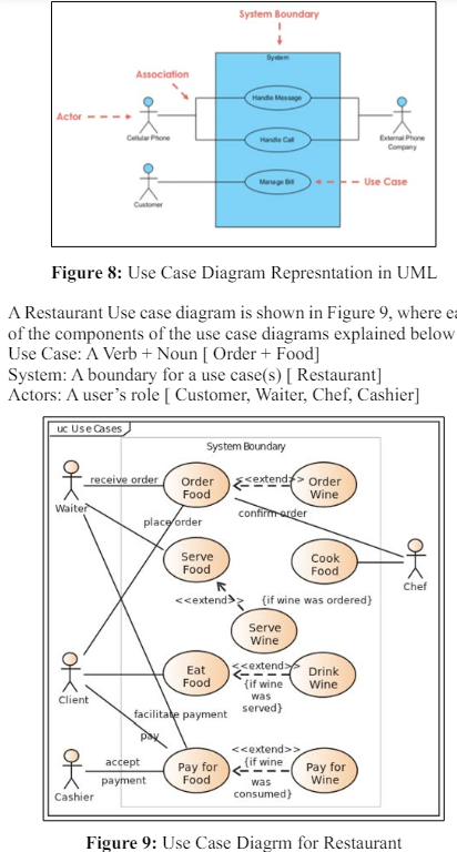
Use case diagram is a way to shown as a graphic depiction of
interactions among system and the users, below are the components
of the use case diagram (Figure 8)
Use Cases are:
• A Verb + Noun
• System function
• It does something
System:
• A boundary for a use case(s)
Actors:
• Something (human/system) that acts.
• A user’s role with respect to the system.
• Are involved in an interaction.
Association
• The relationships between and among the actors and the
use cases
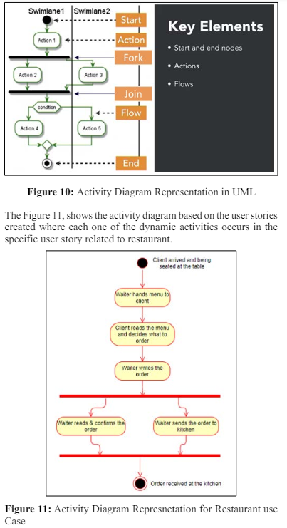
An Activity Diagram is a graphical representation used to model the flow of activities or actions within a system or process. Activity Diagrams are particularly useful for modeling the dynamic aspects of a system, focusing on the behavior of various components and their interactions. Key components of an Activity Diagram (Figure 10) in UML include:
Start and End Nodes: Start node (filled circle) marks the starting point of the activity diagram, while an End node (encircled solid dot) indicates the end or termination of the process
Actions: Actions represent specific tasks that are performed within the system or process. These can include computations, decisions, data processing, or any other discrete operation.
Swimlane: Swimlane are used to organize activities by assigning them to specific actors, roles, or system components. They provide clarity regarding which entity is responsible for executing each activity.
Transitions: Transitions, represented by arrows, show the flow or sequencing of activities. They indicate how one activity leads to another, typically based on conditions or triggers.
Control Nodes: Control nodes, such as decision points (diamond shapes) and merge points, are used to control the flow of activities. Decision points allow for branching paths based on conditions, while merge points combine diverging paths back into a single path.
Forks and Joins: Forks (horizontal bars) represent points in the diagram where multiple activities can occur simultaneously. Joins (hollow bars) indicate synchronization points where multiple paths converge into a single path.
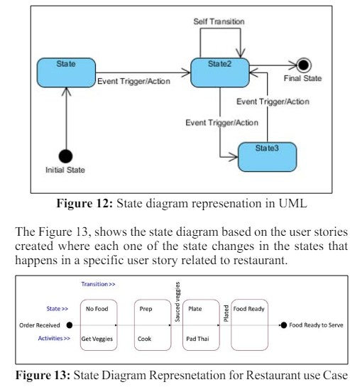
A State Diagram is a graphical representation used to model the dynamic behavior of a system or object over time. State Diagrams (Figure 12) are particularly useful for depicting the various states that an object or system can be in and how it transitions between those states in response to events or conditions.
States: States represent the distinct conditions or situations that an object or system can exist in at any given time. States are typicallydepicted as rounded rectangles with meaningful names, such as "Idle," "Active," or "Error."
Events: Events are external occurrences or stimuli that trigger state transitions. Events can include user actions, system inputs, timers, or other triggers that cause a change in the system's state. Events are typically labeled next to the transition arrow.
Actions: Actions are actions or activities associated with a state or a transition. They specify what happens when an object or system enters or exits a particular state or when a transition occurs. Actions can be represented as text or symbols inside states or next to transitions.
Initial State: An initial state, often depicted as a filled circle, indicates the initial state of the object or system when it is first created or starts its operation.
Final State: A final state, represented by an encircled solid dot, signifies the end of the object's or system's lifecycle or a termination point within the state machine.
In conclusion, this paper has navigate through the intricacies of employing Unified Modeling Language (UML) notations and diagrams to elucidate a business use case within the restaurant industry. We explored business requirement engineering, providing a window into the user's experience and translating this understanding into actionable user stories. The utility of a well-crafted user story was underscored, employing the INVEST acronym to delineate the essential characteristics that ensure clarity and effectiveness.
As we delved deeper into the foundational elements of UML, paper sheds a light on its constituent components such as classes and the nuanced relationships between them-including association, aggregation, and composition. It extended to the conceptual underpinnings of polymorphism and interfaces, essential pillars in the realm of object-oriented programming that foster flexibility and extensibility in system design.
Beyond the basics, we navigated the realm of Object-Oriented Design (OOD) heuristics, which serve as a compass for developers, steering them through the myriad decisions that shape the architecture and design of robust software systems. These guidelines crystallize the collective wisdom of seasoned developers, providing a framework for creating systems that are not only functional but also maintainable and scalable.
The culmination of this theoretical groundwork was the construction of a comprehensive user story rooted in the restaurant use case. This narrative was then brought to life through the creation of corresponding UML diagrams-a use case diagram to capture the interactions within the system, an activity diagram to chronicle the dynamic flow of operations, and a state diagram to visualize the system's various states and transitions.
In synthesizing theory and practice, this paper has not only illuminated the path to effective system design using UML but has also demonstrated its practical application in a real-world context. It stands as a testament to the capability of UML as a transformative tool in the domain of software engineering, offering a blueprint for translating complex business requirements into tangible, operational systems.